
Single-band installation
ULTRA Single Band Repair Clamp. Confirm that the selected clamp matches the pipe and repair geometry shown in this guide.
Check the pipe outside diameter
Check that the actual outside diameter of the damaged pipe falls within the range of the selected clamp.
Clean and prepare the damaged area
Brush off loose dirt. Ensure that exposed edges from the hole, crack or gouge are flush with the pipe outside diameter.
Open the fitting
Unhook the nut-plate and open the fitting.
Wrap and close the clamp
Wrap the clamp around the damaged area. Pull the hand-grip towards the opposite lug-plate and hook the nut-plate over the lug-plate. Loosely tighten the hex nuts to hold the nut-plate in position.
Centre over the damage
Position the clamp centrally over the damaged section of pipe.
Tighten evenly
Tighten the nuts evenly to the recommended bolt torque.
Recheck the torque
After initial tightening, double-check that the correct bolt torque has been achieved.
Torque rating — reference values
| Bolt size | Rating as supplied |
|---|---|
| M12 | 55–70 |
| M16 | 95–110 |
The source table does not state a unit. These figures are not a usable wrench setting until AQUAFITTING confirms the unit and tightening requirement for the supplied clamp. Do not infer or substitute a unit.
Single-band photo sequence
Wrap and engage
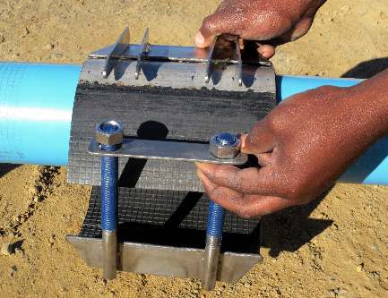
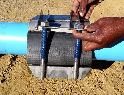
Lock and take up the nuts
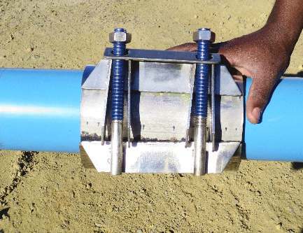
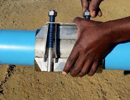
Tighten evenly
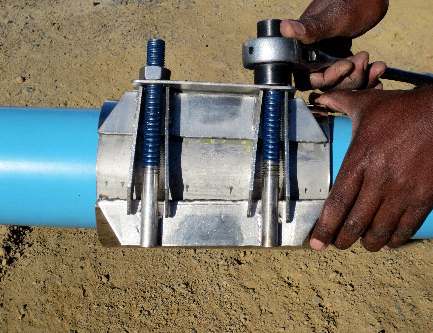
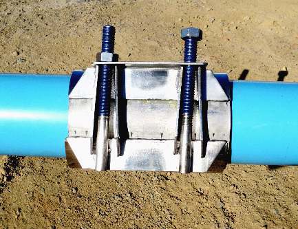
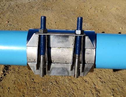
The illustrated application is described as a permanent repair. Confirm the service limits for the actual damage and pipeline condition.
Double-band installation
ULTRA Double Band Repair Clamp. Use the following sequence for the matching plain-shell / studded-shell assembly.
Check the pipe outside diameter
Check that the actual outside diameter of the damaged pipe falls within the range of the selected clamp.
Clean and prepare the damaged area
Brush off loose dirt. Ensure that exposed edges from the hole, crack or gouge are flush with the pipe outside diameter.
Loosen the nuts
Loosen the hex nuts as far as the protection caps.
Separate the shells
Unhook and separate the plain shell and studded body shell.
Fit both body shells
Place the plain body shell over the damaged area. Hook the nut-plate of the studded body shell over the lug-plates of the plain body shell. Loosely tighten the nuts to hold the fitting together.
Centre, tighten and recheck
Ensure that the clamp is centred over the damaged area. Tighten the nuts evenly to the recommended bolt torque. Finally, check that the correct torque has been achieved on all bolts.
Torque rating — reference values
| Bolt size | Rating as supplied |
|---|---|
| M12 | 55–70 |
| M16 | 95–110 |
The source table does not state a unit. These figures are not a usable wrench setting until AQUAFITTING confirms the unit and tightening requirement for the supplied clamp. Do not infer or substitute a unit.
Component identification
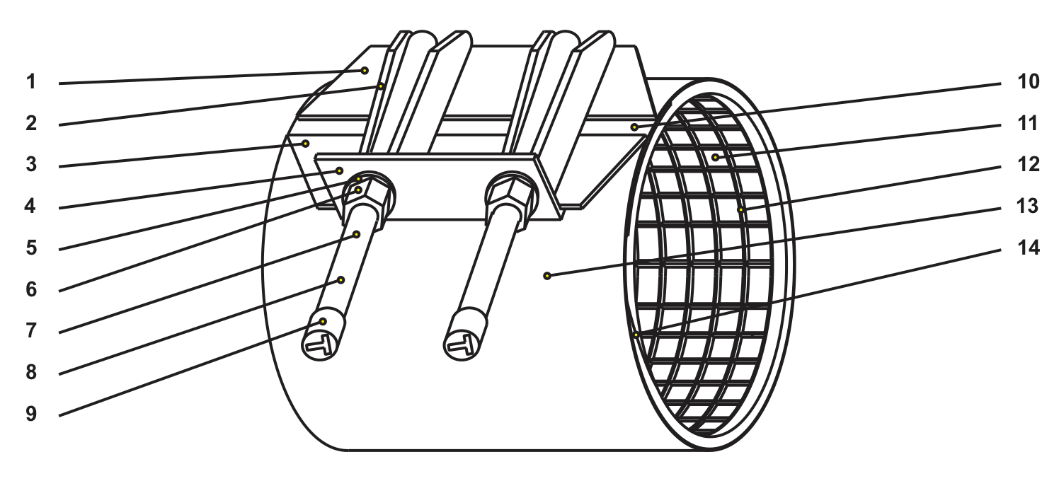
Component key
| No. | Component | No. | Component |
|---|---|---|---|
| 1 | Side Bars | 8 | Stud Coating |
| 2 | Fingers | 9 | Protective Thread Cap |
| 3 | Side Bars | 10 | Armour Plate |
| 4 | Locking Washer Plate | 11 | Rubber |
| 5 | Washer | 12 | 45° Angled ribs |
| 6 | Nuts | 13 | Shell |
| 7 | Studs | 14 | Tapered Rubber Ends |
Positions 1 and 3 are both designated Side Bars. Material grades and pressure rating are not specified by this component drawing.
Keep the matching document with the product.
Use the guide for the supplied configuration. For project-specific requirements, contact aquafitting@gmail.com and quote AQF-IG-RC-001.