
Preparation and sealing
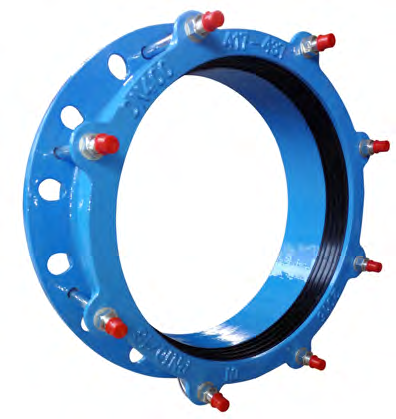
Examine the pipe end
Ensure the pipe end is round, smooth and free from bulges, dents, score marks, scale, rust and loose debris. Check that the pipe diameter is within the range provided for the adaptor. Weld beads must be ground flush while maintaining the correct surface profile.
Check the gasket grade
Check that the grade of gasket is suitable for the conveyed medium.
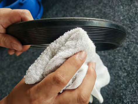
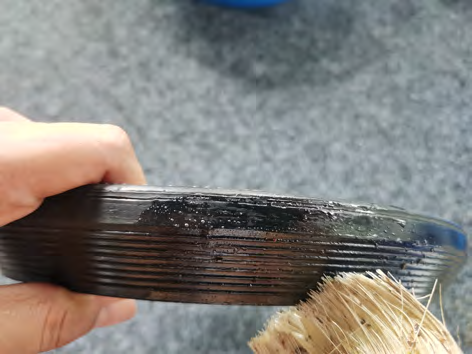
Check seal lubrication
Check that the outer tapered face of the rubber seal is sufficiently lubricated where it contacts the adaptor body casting. If not, apply a suitable lubricant. Lubrication prevents the rubber from pinching between the adaptor end ring and cast body and assists installation.
Positioning and tightening
Align and mark
Align the product with the pipe already in position. Mark the pipe end at a distance equal to or greater than the overall assembled width of the adaptor. Place the adaptor wholly on one pipe end.
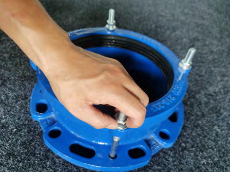
Position and finger-tighten
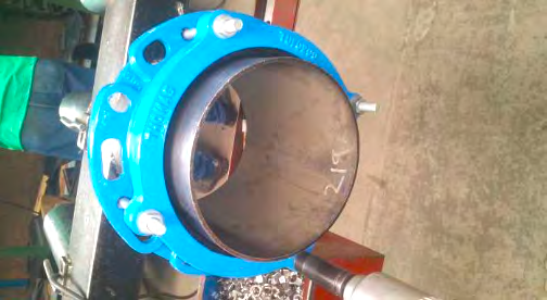
Adjust the setting gap between pipe ends as necessary. Using the marks made in Step 4, position the adaptor over the pipe end and finger-tighten the bolts equally. Finger-tightening allows the installer to centre the product around the pipe.
Tighten opposite bolts progressively
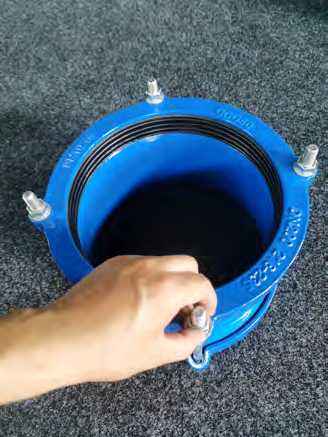
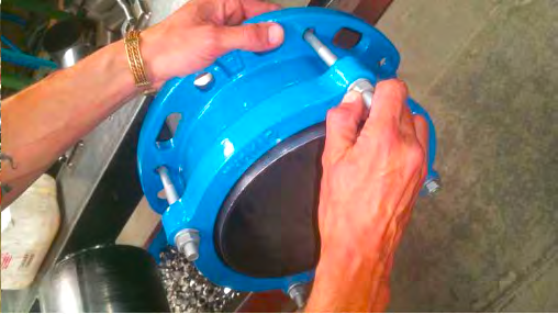
Tighten diametrically opposed bolts, giving the nuts one or two turns at a time to draw up the end ring evenly. Tighten to the specified torque, working around the adaptor as many times as necessary. The radial gap between the pipe and adaptor end ring should be even all the way round. Rubber may be seen to extrude into the gap.
Bolt torque rating
| Bolt size | Torque (Nm) |
|---|---|
| M12 | 70–80 |
| M14 | 90–100 |
| M16 | 100–120 |
Tighten in diametrically opposite pairs. The source torque section specifies 2 or 3 turns per pass; the installation step specifies 1 or 2 turns. In both sections, the end ring is drawn up evenly to the prescribed final torque.
Size reference
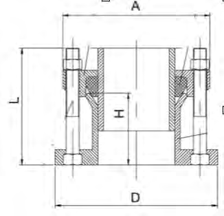
Size and range reference
| SIZE | RANGE | A | D | L | Qty |
|---|---|---|---|---|---|
| DN40 | 48-63 | 165 | 165 | M12*130 | 2 |
| DN50 | 59-72 | 180 | 187 | M12*130 | 2 |
| DN65 | 72-85 | 180 | 222 | M12*130 | 2 |
| DN80 | 88-103 | 190 | 227 | M12*130 | 4 |
| DN100 | 93-117 | 204 | 227 | M12*130 | 4 |
| DN100 | 107-128 | 214 | 227 | M12*130 | 4 |
| DN125 | 138-153 | 250 | 287 | M12*130 | 4 |
| DN150 | 155-175 | 278 | 287 | M12*140 | 4 |
| DN150 | 159-182 | 278 | 287 | M12*140 | 4 |
| DN175 | 192-210 | 300 | 340 | M12*140 | 4 |
| DN200 | 218-235 | 324 | 340 | M12*140 | 4 |
| DN225 | 250-267 | 406 | 402 | M12*140 | 4 |
| DN250 | 235-252 | 406 | 402 | M12*140 | 4 |
| DN250 | 271-289 | 406 | 406 | M12*140 | 4 |
| DN300 | 315-332 | 440 | 482 | M12*140 | 6 |
| DN300 | 322-339 | 452 | 482 | M12*140 | 6 |
| DN300 | 324-350 | 463 | 482 | M12*140 | 6 |
| DN300 | 345-375 | 510 | 520 | M12*180 | 8 |
| DN350 | 374-391 | 510 | 520 | M16*180 | 8 |
| DN400 | 400-429 | 560 | 580 | M16*180 | 8 |
| DN400 | 417-437 | 560 | 580 | M16*180 | 8 |
| DN400 | 455-472 | 560 | 580 | M16*180 | 8 |
| DN450 | 480-500 | 630 | 640 | M16*180 | 10 |
| DN500 | 500-535 | 700 | 715 | M16*180 | 10 |
| DN500 | 526-546 | 700 | 715 | M16*180 | 10 |
| DN500 | 555-572 | 700 | 715 | M16*180 | 10 |
| DN600 | 600-630 | 830 | 840 | M16*180 | 10 |
| DN600 | 630-650 | 830 | 840 | M16*180 | 10 |
Original headings and values are retained. The L column contains bolt designations such as M12*130. The source does not define every dimension symbol or give a unit for every column. Confirm the current drawing and column mapping before dimensional use.
Keep the matching document with the product.
Use the guide for the supplied configuration. For project-specific requirements, contact aquafitting@gmail.com and quote AQF-IG-UFA-001.