top of page

Double-Flanged 22.5° Bend

Change pipeline direction through 22.5° between two flanges. Specify the bend angle and flange size together.

Connection interface
Connects to a compatible mating flange. Select by flange DN, drilling, gasket and service conditions; the flange interface does not imply compatibility with every pipe material.
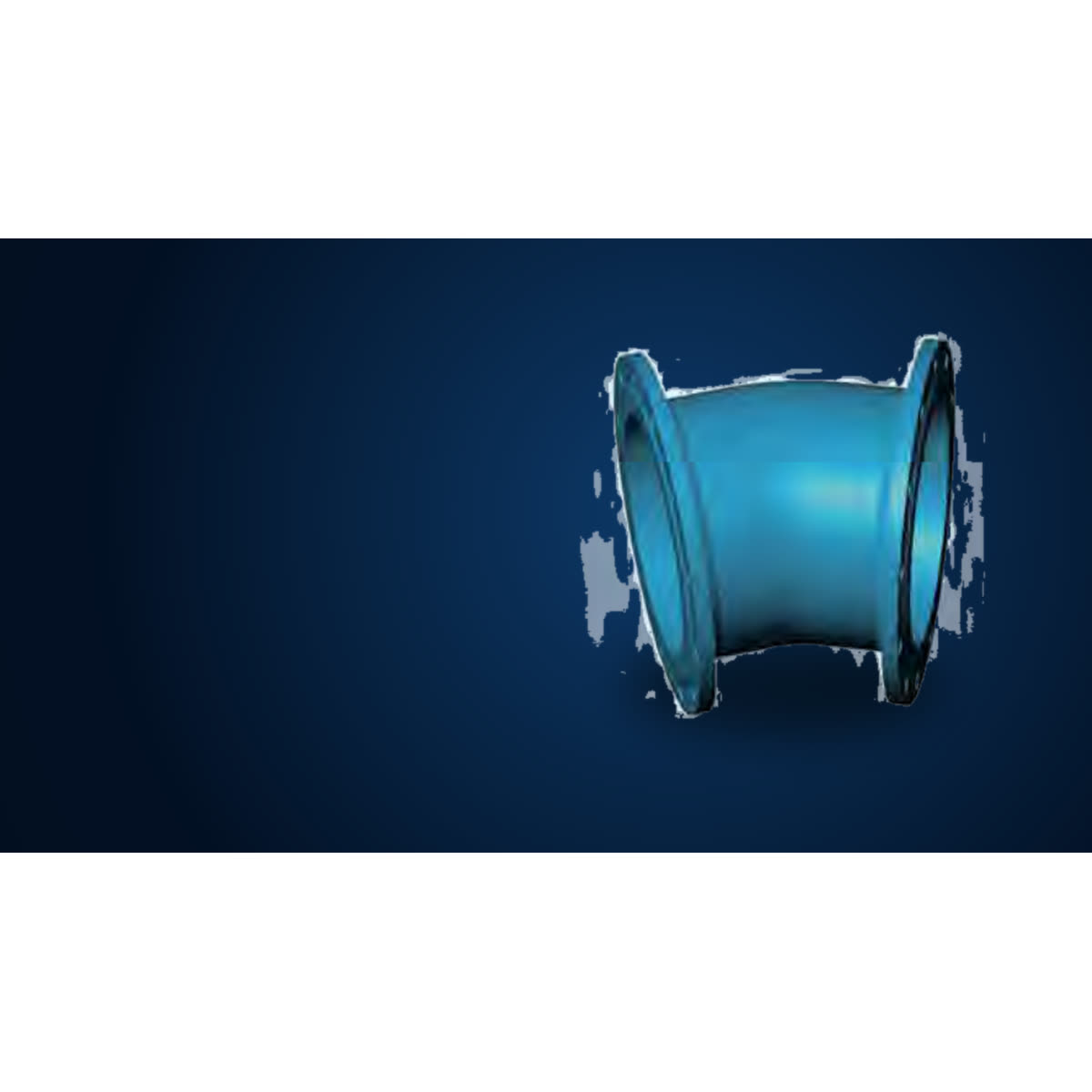
Product overview

Change pipeline direction through 22.5° between two flanges.

Connection interface

Connects to a compatible mating flange. Select by flange DN, drilling, gasket and service conditions; the flange interface does not imply compatibility with every pipe material.

Connection arrangement

Flange → 22.5° bend → flange

Request a Quote

Connection and selection

22.5° direction change

Match the bend angle to the pipeline route. Check the drawing for installation length and clearance.

Flange interface

Match the flange DN and drilling to the mating component. Select the gasket and fasteners for the specified assembly.

Size and installation

Check the product-specific drawing for the required lengths and clearances. Confirm current pressure applicability and available sizes for the project.

Request a Quote

Catalogue dimensions

Source: AQUAFITTING fixed-flange and T-type joint catalogue, page 20. Dimension symbols follow the corresponding source drawing. Confirm the selected configuration and current dimensions before ordering. The source lists alternative lengths for some nominal sizes. Select the matching drawing. DN1800 and DN2000 lengths need confirmation and are not adopted.

Double-Flanged 22.5° Bend — Catalogue dimensions
DNeL
807.0105
807.0130
1007.2110
1007.2140
1507.8109
1507.8160
2008.4131
2008.4180
2509.0190
2509.0350
3009.6210
3009.6400
35010.2210
35010.2298
40010.8239
40010.8324
45011.4349
50012.0375
60013.2426
70014.4478
80015.6529
90016.8581
100018.0632
110019.2683
120020.4735
140022.8835
150024.0880
160025.2940
180027.6—
200030—

Technical Downloads

Product FAQs

What should I send for a Double-Flanged 22.5° Bend enquiry?

Send the required DN/OD and any main/branch or inlet/outlet size, working pressure, flange drilling or socket/pipe details, quantity, destination and any project drawing or document requirement.

What technical evidence is available for Double-Flanged 22.5° Bend?

Our catalogue reference (ISO2531 fixed-flange catalogue page 20) shows DN, e and L rows plus Mass columns labelled PN10, PN16 and PN25, with product drawing. Dimensions are confirmed against your enquiry before quotation.

Which details still require Aquafitting confirmation?

Confirm current size availability, working pressure, material, gasket, coating, flange drilling or socket/pipe interface, dimensions, mass, standard applicability, documents and project suitability before quotation.

Product selection

product name; required DN/OD and any main/branch or inlet/outlet size; working pressure or pressure class; flange drilling or socket/pipe details; material/coating requirement; quantity; destination; required documents; project drawing if available

Request a Quote

Double-Flanged 22.5° Bend

Aquafitting Double-Flanged 22.5° Bend product view on a controlled background.

Change pipeline direction through 22.5° between two flanges. Specify the bend angle and flange size together.

Connection interface
Connects to a compatible mating flange. Select by flange DN, drilling, gasket and service conditions; the flange interface does not imply compatibility with every pipe material.

Product summary · PDF · English

Request a Quote

Overview

Catalogue dimensions

DN
e
L
80
7.0
105
80
7.0
130
100
7.2
110
100
7.2
140
150
7.8
109
150
7.8
160
200
8.4
131
200
8.4
180
250
9.0
190
250
9.0
350
300
9.6
210
300
9.6
400
350
10.2
210
350
10.2
298
400
10.8
239
400
10.8
324
450
11.4
349
500
12.0
375
600
13.2
426
700
14.4
478
800
15.6
529
900
16.8
581
1000
18.0
632
1100
19.2
683
1200
20.4
735
1400
22.8
835
1500
24.0
880
1600
25.2
940
1800
27.6
—
2000
30
—

Source: AQUAFITTING fixed-flange and T-type joint catalogue, page 20. Dimension symbols follow the corresponding source drawing. Confirm the selected configuration and current dimensions before ordering. The source lists alternative lengths for some nominal sizes. Select the matching drawing. DN1800 and DN2000 lengths need confirmation and are not adopted.

80

e: 7.0 · L: 105

80

e: 7.0 · L: 130

100

e: 7.2 · L: 110

100

e: 7.2 · L: 140

150

e: 7.8 · L: 109

150

e: 7.8 · L: 160

200

e: 8.4 · L: 131

200

e: 8.4 · L: 180

250

e: 9.0 · L: 190

250

e: 9.0 · L: 350

300

e: 9.6 · L: 210

300

e: 9.6 · L: 400

350

e: 10.2 · L: 210

350

e: 10.2 · L: 298

400

e: 10.8 · L: 239

400

e: 10.8 · L: 324

450

e: 11.4 · L: 349

500

e: 12.0 · L: 375

600

e: 13.2 · L: 426

700

e: 14.4 · L: 478

800

e: 15.6 · L: 529

900

e: 16.8 · L: 581

1000

e: 18.0 · L: 632

1100

e: 19.2 · L: 683

1200

e: 20.4 · L: 735

1400

e: 22.8 · L: 835

1500

e: 24.0 · L: 880

1600

e: 25.2 · L: 940

1800

e: 27.6 · L: —

2000

e: 30 · L: —

Product overview

Change pipeline direction through 22.5° between two flanges.

Connection interface

Connects to a compatible mating flange. Select by flange DN, drilling, gasket and service conditions; the flange interface does not imply compatibility with every pipe material.

Connection arrangement

Flange → 22.5° bend → flange

Request a Quote

Technical evidence

Review the product identity and available resources, then send the required size or measured outside diameter, pipe material, connection details, operating conditions, quantity, destination and supporting files.

Double-Flanged 22.5° Bend catalogue drawing, available on request.
Double-Flanged 22.5° Bend catalogue dimension table, available on request.

Connection and selection

22.5° direction change

Match the bend angle to the pipeline route. Check the drawing for installation length and clearance.

Flange interface

Match the flange DN and drilling to the mating component. Select the gasket and fasteners for the specified assembly.

Size and installation

Check the product-specific drawing for the required lengths and clearances. Confirm current pressure applicability and available sizes for the project.

Request a Quote

Product selection

product name; required DN/OD and any main/branch or inlet/outlet size; working pressure or pressure class; flange drilling or socket/pipe details; material/coating requirement; quantity; destination; required documents; project drawing if available
Request a Quote

Product FAQs

What should I send for a Double-Flanged 22.5° Bend enquiry?

Send the required DN/OD and any main/branch or inlet/outlet size, working pressure, flange drilling or socket/pipe details, quantity, destination and any project drawing or document requirement.

What technical evidence is available for Double-Flanged 22.5° Bend?

Our catalogue reference (ISO2531 fixed-flange catalogue page 20) shows DN, e and L rows plus Mass columns labelled PN10, PN16 and PN25, with product drawing. Dimensions are confirmed against your enquiry before quotation.

Which details still require Aquafitting confirmation?

Confirm current size availability, working pressure, material, gasket, coating, flange drilling or socket/pipe interface, dimensions, mass, standard applicability, documents and project suitability before quotation.

Materials & standards

Body
Ductile iron EN-GJS-450-10 or EN-GJS-500-7


Gaskets (where supplied)
EPDM (WRAS approved material) or NBR


Bolts and nuts (where supplied)
Zinc-plated carbon steel, Dacromet-coated or stainless steel


Coating
Epoxy powder coating, 250 μm nominal (WRAS approved material)


Pressure rating
PN10, PN16, PN25 or PN40, as shown in the size table for each model


Standard
ISO 2531


Material, bolt and coating options are confirmed in the quotation.
View certificates →

Double-Flanged 90° Duck Foot Bend

Double-Flanged 90° Duck Foot Bend

Fixed Flange Fittings

Double-Flanged 90° Duck Foot Bend for 90-degree duck-foot bend enquiries requiring base and flange review. Send the required sizes, working pressure, connection details and project drawing for review.

Double-Flanged 45° Bend

Double-Flanged 45° Bend

Fixed Flange Fittings

Double-Flanged 45° Bend for 45-degree fixed-flange direction-change enquiries. Send the required sizes, working pressure, connection details and project drawing for review.

Double-Flanged 11.25° Bend

Double-Flanged 11.25° Bend

Fixed Flange Fittings

Double-Flanged 11.25° Bend for 11.25-degree fixed-flange direction-change enquiries. Send the required sizes, working pressure, connection details and project drawing for review.

All-Flanged Tees

All-Flanged Tees

Fixed Flange Fittings

All-Flanged Tees for fixed-flange branch enquiries with specified main and branch sizes. Send the required sizes, working pressure, connection details and project drawing for review.

bottom of page