Resilient-Seated Flanged Gate Valve — F4
Isolate flow between flanged pipeline components. Select the F4 installation-length pattern and the required valve size.
Connection interface
Connects to a compatible mating flange. Select by flange DN, drilling, gasket and service conditions; the flange interface does not imply compatibility with every pipe material.
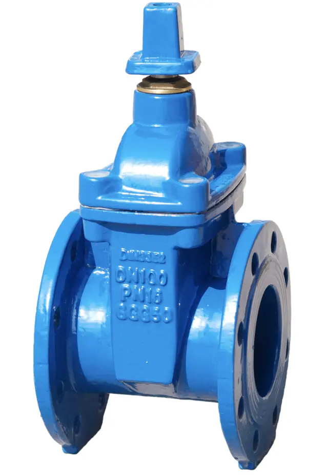
Product overview
Isolate flow between flanged pipeline components.
Connection interface
Connects to a compatible mating flange. Select by flange DN, drilling, gasket and service conditions; the flange interface does not imply compatibility with every pipe material.
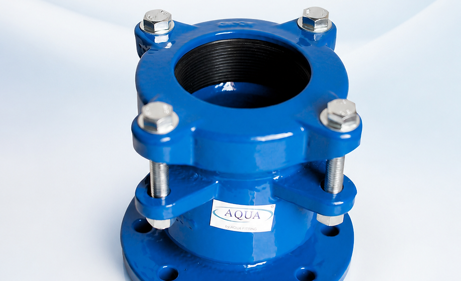
Connection arrangement
Flange → resilient-seated gate valve → flange
Connection and selection
Isolation valve
Match the valve to the required isolation point and service conditions.
Installation pattern
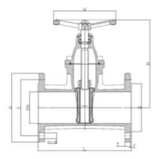
Use the F4 drawing to confirm the installation length. F4 and F5 are not interchangeable solely because nominal size is the same.
Mating flanges
Confirm flange DN, drilling and the selected valve pressure configuration.
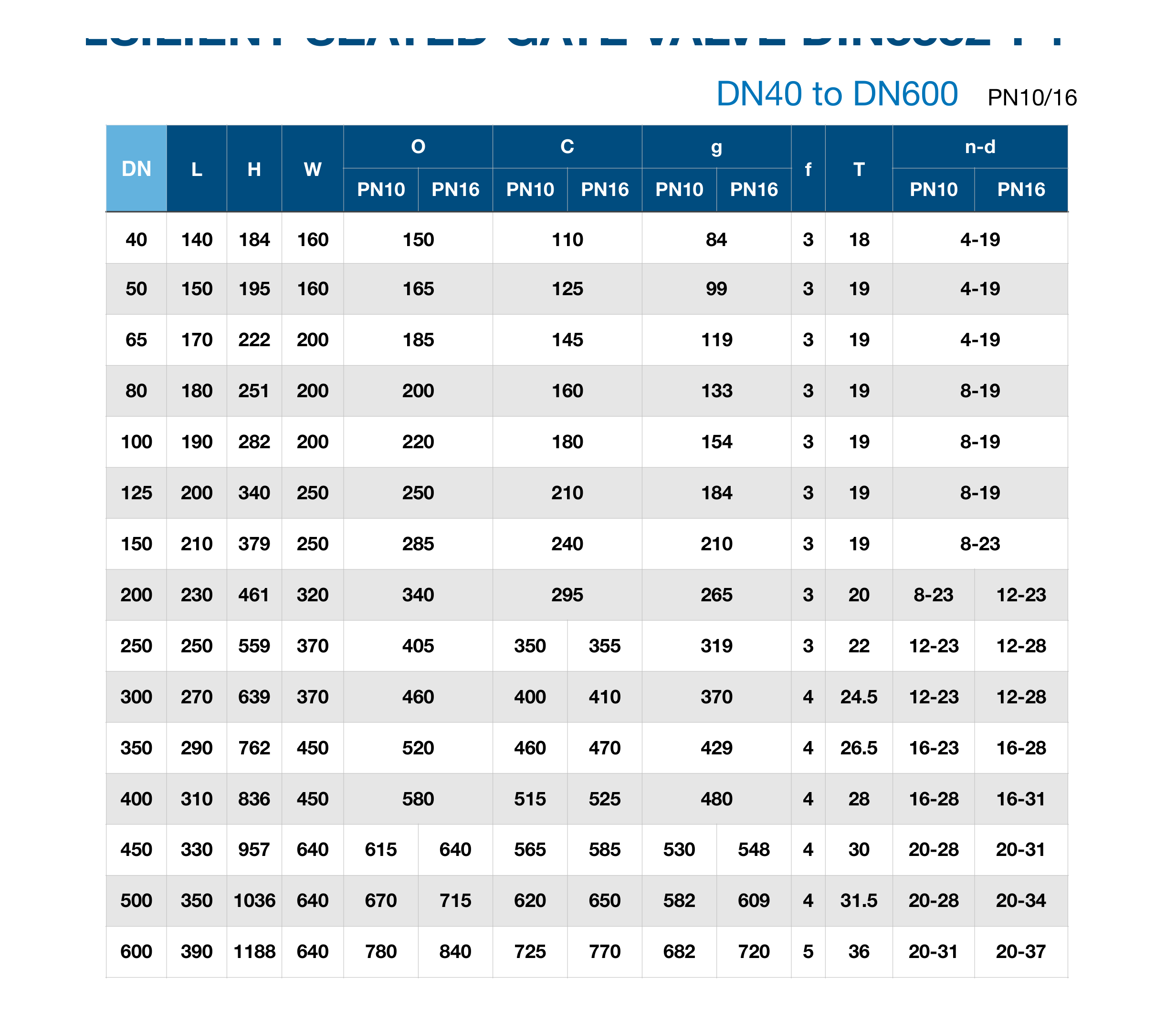
Catalogue dimensions
Source: AQUAFITTING English catalogue 2023, page 37. Dimension symbols follow the corresponding source drawing. Confirm the selected configuration and current dimensions before ordering. F4 and F5 have different face-to-face L dimensions.
| DN | Flange table | L | H | W | O | C | g | f | T | n–d |
|---|---|---|---|---|---|---|---|---|---|---|
| 40 | PN10 | 140 | 184 | 160 | 150 | 110 | 84 | 3 | 18 | 4-19 |
| 40 | PN16 | 140 | 184 | 160 | 150 | 110 | 84 | 3 | 18 | 4-19 |
| 50 | PN10 | 150 | 195 | 160 | 165 | 125 | 99 | 3 | 19 | 4-19 |
| 50 | PN16 | 150 | 195 | 160 | 165 | 125 | 99 | 3 | 19 | 4-19 |
| 65 | PN10 | 170 | 222 | 200 | 185 | 145 | 119 | 3 | 19 | 4-19 |
| 65 | PN16 | 170 | 222 | 200 | 185 | 145 | 119 | 3 | 19 | 4-19 |
| 80 | PN10 | 180 | 251 | 200 | 200 | 160 | 133 | 3 | 19 | 8-19 |
| 80 | PN16 | 180 | 251 | 200 | 200 | 160 | 133 | 3 | 19 | 8-19 |
| 100 | PN10 | 190 | 282 | 200 | 220 | 180 | 154 | 3 | 19 | 8-19 |
| 100 | PN16 | 190 | 282 | 200 | 220 | 180 | 154 | 3 | 19 | 8-19 |
| 125 | PN10 | 200 | 340 | 250 | 250 | 210 | 184 | 3 | 19 | 8-19 |
| 125 | PN16 | 200 | 340 | 250 | 250 | 210 | 184 | 3 | 19 | 8-19 |
| 150 | PN10 | 210 | 379 | 250 | 285 | 240 | 210 | 3 | 19 | 8-23 |
| 150 | PN16 | 210 | 379 | 250 | 285 | 240 | 210 | 3 | 19 | 8-23 |
| 200 | PN10 | 230 | 461 | 320 | 340 | 295 | 265 | 3 | 20 | 8-23 |
| 200 | PN16 | 230 | 461 | 320 | 340 | 295 | 265 | 3 | 20 | 12-23 |
| 250 | PN10 | 250 | 559 | 370 | 405 | 350 | 319 | 3 | 22 | 12-23 |
| 250 | PN16 | 250 | 559 | 370 | 405 | 355 | 319 | 3 | 22 | 12-28 |
| 300 | PN10 | 270 | 639 | 370 | 460 | 400 | 370 | 4 | 24.5 | 12-23 |
| 300 | PN16 | 270 | 639 | 370 | 460 | 410 | 370 | 4 | 24.5 | 12-28 |
| 350 | PN10 | 290 | 762 | 450 | 520 | 460 | 429 | 4 | 26.5 | 16-23 |
| 350 | PN16 | 290 | 762 | 450 | 520 | 470 | 429 | 4 | 26.5 | 16-28 |
| 400 | PN10 | 310 | 836 | 450 | 580 | 515 | 480 | 4 | 28 | 16-28 |
| 400 | PN16 | 310 | 836 | 450 | 580 | 525 | 480 | 4 | 28 | 16-31 |
| 450 | PN10 | 330 | 957 | 640 | 615 | 565 | 530 | 4 | 30 | 20-28 |
| 450 | PN16 | 330 | 957 | 640 | 640 | 585 | 548 | 4 | 30 | 20-31 |
| 500 | PN10 | 350 | 1036 | 640 | 670 | 620 | 582 | 4 | 31.5 | 20-28 |
| 500 | PN16 | 350 | 1036 | 640 | 715 | 650 | 609 | 4 | 31.5 | 20-34 |
| 600 | PN10 | 390 | 1188 | 640 | 780 | 725 | 682 | 5 | 36 | 20-31 |
| 600 | PN16 | 390 | 1188 | 640 | 840 | 770 | 720 | 5 | 36 | 20-37 |
Technical evidence
Review the product identity and available resources, then send the required size or measured outside diameter, pipe material, connection details, operating conditions, quantity, destination and supporting files.
Technical Downloads
Product selection
product name; DN or nominal size; end connection requirement; pipe material; working pressure; operation requirement; quantity; destination