top of page

Resilient-Seated Flanged Gate Valve — F5

Isolate flow between flanged pipeline components. Select the F5 installation-length pattern and the required valve size.

Connection interface
Connects to a compatible mating flange. Select by flange DN, drilling, gasket and service conditions; the flange interface does not imply compatibility with every pipe material.
Product overview

Isolate flow between flanged pipeline components.

Connection interface

Connects to a compatible mating flange. Select by flange DN, drilling, gasket and service conditions; the flange interface does not imply compatibility with every pipe material.

Connection arrangement

Flange → resilient-seated gate valve → flange

Request a Quote

Connection and selection

Isolation valve

Match the valve to the required isolation point and service conditions.

Installation pattern

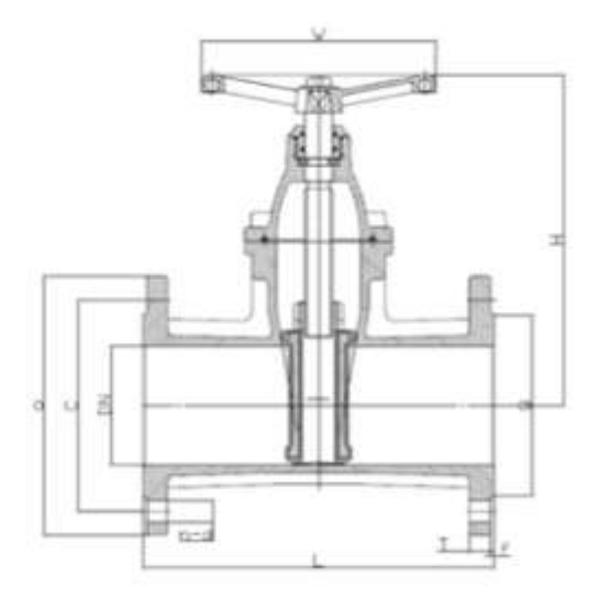
Use the F5 drawing to confirm the installation length. F4 and F5 are not interchangeable solely because nominal size is the same.

Mating flanges

Confirm flange DN, drilling and the selected valve pressure configuration.

Request a Quote

Catalogue dimensions

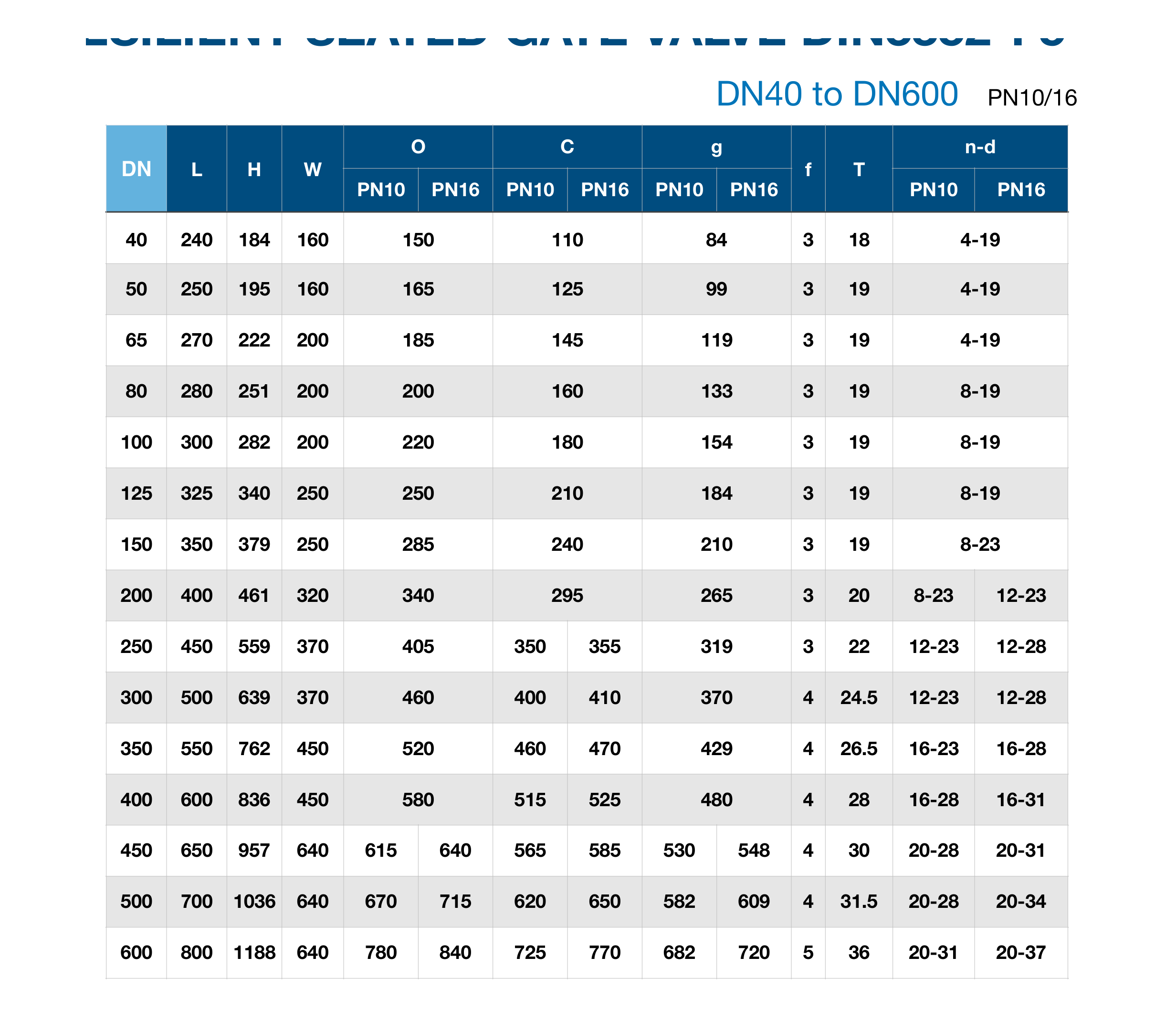
Source: AQUAFITTING English catalogue 2023, page 38. Dimension symbols follow the corresponding source drawing. Confirm the selected configuration and current dimensions before ordering. F4 and F5 have different face-to-face L dimensions.

Resilient-Seated Flanged Gate Valve — F5 — Catalogue dimensions
DNFlange tableLHWOCgfTn–d
40PN10240184160150110843184-19
40PN16240184160150110843184-19
50PN10250195160165125993194-19
50PN16250195160165125993194-19
65PN102702222001851451193194-19
65PN162702222001851451193194-19
80PN102802512002001601333198-19
80PN162802512002001601333198-19
100PN103002822002201801543198-19
100PN163002822002201801543198-19
125PN103253402502502101843198-19
125PN163253402502502101843198-19
150PN103503792502852402103198-23
150PN163503792502852402103198-23
200PN104004613203402952653208-23
200PN1640046132034029526532012-23
250PN1045055937040535031932212-23
250PN1645055937040535531932212-28
300PN10500639370460400370424.512-23
300PN16500639370460410370424.512-28
350PN10550762450520460429426.516-23
350PN16550762450520470429426.516-28
400PN1060083645058051548042816-28
400PN1660083645058052548042816-31
450PN1065095764061556553043020-28
450PN1665095764064058554843020-31
500PN107001036640670620582431.520-28
500PN167001036640715650609431.520-34
600PN10800118864078072568253620-31
600PN16800118864084077072053620-37

Technical evidence

Review the product identity and available resources, then send the required size or measured outside diameter, pipe material, connection details, operating conditions, quantity, destination and supporting files.

Technical Downloads

Product selection

product name; DN or nominal size; end connection requirement; pipe material; working pressure; operation requirement; quantity; destination

Request a Quote

Resilient-Seated Flanged Gate Valve — F5

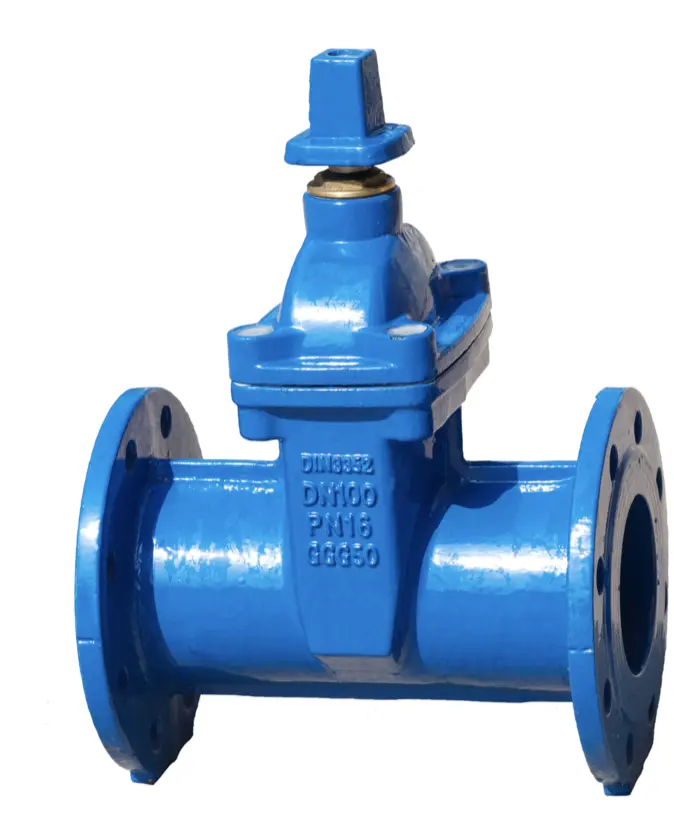
Aquafitting RESILIENT SEATED GATE VALVE DIN3352-F5 product view.

Isolate flow between flanged pipeline components. Select the F5 installation-length pattern and the required valve size.

Connection interface
Connects to a compatible mating flange. Select by flange DN, drilling, gasket and service conditions; the flange interface does not imply compatibility with every pipe material.

Product summary · PDF · English · V2026.08 · 96 KB

Request a Quote

Overview

Catalogue dimensions

DN
Flange table
L
H
W
O
C
g
f
T
n–d
40
PN10
240
184
160
150
110
84
3
18
4-19
40
PN16
240
184
160
150
110
84
3
18
4-19
50
PN10
250
195
160
165
125
99
3
19
4-19
50
PN16
250
195
160
165
125
99
3
19
4-19
65
PN10
270
222
200
185
145
119
3
19
4-19
65
PN16
270
222
200
185
145
119
3
19
4-19
80
PN10
280
251
200
200
160
133
3
19
8-19
80
PN16
280
251
200
200
160
133
3
19
8-19
100
PN10
300
282
200
220
180
154
3
19
8-19
100
PN16
300
282
200
220
180
154
3
19
8-19
125
PN10
325
340
250
250
210
184
3
19
8-19
125
PN16
325
340
250
250
210
184
3
19
8-19
150
PN10
350
379
250
285
240
210
3
19
8-23
150
PN16
350
379
250
285
240
210
3
19
8-23
200
PN10
400
461
320
340
295
265
3
20
8-23
200
PN16
400
461
320
340
295
265
3
20
12-23
250
PN10
450
559
370
405
350
319
3
22
12-23
250
PN16
450
559
370
405
355
319
3
22
12-28
300
PN10
500
639
370
460
400
370
4
24.5
12-23
300
PN16
500
639
370
460
410
370
4
24.5
12-28
350
PN10
550
762
450
520
460
429
4
26.5
16-23
350
PN16
550
762
450
520
470
429
4
26.5
16-28
400
PN10
600
836
450
580
515
480
4
28
16-28
400
PN16
600
836
450
580
525
480
4
28
16-31
450
PN10
650
957
640
615
565
530
4
30
20-28
450
PN16
650
957
640
640
585
548
4
30
20-31
500
PN10
700
1036
640
670
620
582
4
31.5
20-28
500
PN16
700
1036
640
715
650
609
4
31.5
20-34
600
PN10
800
1188
640
780
725
682
5
36
20-31
600
PN16
800
1188
640
840
770
720
5
36
20-37

Source: AQUAFITTING English catalogue 2023, page 38. Dimension symbols follow the corresponding source drawing. Confirm the selected configuration and current dimensions before ordering. F4 and F5 have different face-to-face L dimensions.

40

Flange table: PN10 · L: 240 · H: 184 · W: 160 · O: 150 · C: 110 · g: 84 · f: 3 · T: 18 · n–d: 4-19

40

Flange table: PN16 · L: 240 · H: 184 · W: 160 · O: 150 · C: 110 · g: 84 · f: 3 · T: 18 · n–d: 4-19

50

Flange table: PN10 · L: 250 · H: 195 · W: 160 · O: 165 · C: 125 · g: 99 · f: 3 · T: 19 · n–d: 4-19

50

Flange table: PN16 · L: 250 · H: 195 · W: 160 · O: 165 · C: 125 · g: 99 · f: 3 · T: 19 · n–d: 4-19

65

Flange table: PN10 · L: 270 · H: 222 · W: 200 · O: 185 · C: 145 · g: 119 · f: 3 · T: 19 · n–d: 4-19

65

Flange table: PN16 · L: 270 · H: 222 · W: 200 · O: 185 · C: 145 · g: 119 · f: 3 · T: 19 · n–d: 4-19

80

Flange table: PN10 · L: 280 · H: 251 · W: 200 · O: 200 · C: 160 · g: 133 · f: 3 · T: 19 · n–d: 8-19

80

Flange table: PN16 · L: 280 · H: 251 · W: 200 · O: 200 · C: 160 · g: 133 · f: 3 · T: 19 · n–d: 8-19

100

Flange table: PN10 · L: 300 · H: 282 · W: 200 · O: 220 · C: 180 · g: 154 · f: 3 · T: 19 · n–d: 8-19

100

Flange table: PN16 · L: 300 · H: 282 · W: 200 · O: 220 · C: 180 · g: 154 · f: 3 · T: 19 · n–d: 8-19

125

Flange table: PN10 · L: 325 · H: 340 · W: 250 · O: 250 · C: 210 · g: 184 · f: 3 · T: 19 · n–d: 8-19

125

Flange table: PN16 · L: 325 · H: 340 · W: 250 · O: 250 · C: 210 · g: 184 · f: 3 · T: 19 · n–d: 8-19

150

Flange table: PN10 · L: 350 · H: 379 · W: 250 · O: 285 · C: 240 · g: 210 · f: 3 · T: 19 · n–d: 8-23

150

Flange table: PN16 · L: 350 · H: 379 · W: 250 · O: 285 · C: 240 · g: 210 · f: 3 · T: 19 · n–d: 8-23

200

Flange table: PN10 · L: 400 · H: 461 · W: 320 · O: 340 · C: 295 · g: 265 · f: 3 · T: 20 · n–d: 8-23

200

Flange table: PN16 · L: 400 · H: 461 · W: 320 · O: 340 · C: 295 · g: 265 · f: 3 · T: 20 · n–d: 12-23

250

Flange table: PN10 · L: 450 · H: 559 · W: 370 · O: 405 · C: 350 · g: 319 · f: 3 · T: 22 · n–d: 12-23

250

Flange table: PN16 · L: 450 · H: 559 · W: 370 · O: 405 · C: 355 · g: 319 · f: 3 · T: 22 · n–d: 12-28

300

Flange table: PN10 · L: 500 · H: 639 · W: 370 · O: 460 · C: 400 · g: 370 · f: 4 · T: 24.5 · n–d: 12-23

300

Flange table: PN16 · L: 500 · H: 639 · W: 370 · O: 460 · C: 410 · g: 370 · f: 4 · T: 24.5 · n–d: 12-28

350

Flange table: PN10 · L: 550 · H: 762 · W: 450 · O: 520 · C: 460 · g: 429 · f: 4 · T: 26.5 · n–d: 16-23

350

Flange table: PN16 · L: 550 · H: 762 · W: 450 · O: 520 · C: 470 · g: 429 · f: 4 · T: 26.5 · n–d: 16-28

400

Flange table: PN10 · L: 600 · H: 836 · W: 450 · O: 580 · C: 515 · g: 480 · f: 4 · T: 28 · n–d: 16-28

400

Flange table: PN16 · L: 600 · H: 836 · W: 450 · O: 580 · C: 525 · g: 480 · f: 4 · T: 28 · n–d: 16-31

450

Flange table: PN10 · L: 650 · H: 957 · W: 640 · O: 615 · C: 565 · g: 530 · f: 4 · T: 30 · n–d: 20-28

450

Flange table: PN16 · L: 650 · H: 957 · W: 640 · O: 640 · C: 585 · g: 548 · f: 4 · T: 30 · n–d: 20-31

500

Flange table: PN10 · L: 700 · H: 1036 · W: 640 · O: 670 · C: 620 · g: 582 · f: 4 · T: 31.5 · n–d: 20-28

500

Flange table: PN16 · L: 700 · H: 1036 · W: 640 · O: 715 · C: 650 · g: 609 · f: 4 · T: 31.5 · n–d: 20-34

600

Flange table: PN10 · L: 800 · H: 1188 · W: 640 · O: 780 · C: 725 · g: 682 · f: 5 · T: 36 · n–d: 20-31

600

Flange table: PN16 · L: 800 · H: 1188 · W: 640 · O: 840 · C: 770 · g: 720 · f: 5 · T: 36 · n–d: 20-37

Product overview

Isolate flow between flanged pipeline components.

Connection interface

Connects to a compatible mating flange. Select by flange DN, drilling, gasket and service conditions; the flange interface does not imply compatibility with every pipe material.

Connection arrangement

Flange → resilient-seated gate valve → flange

Request a Quote

Technical evidence

Review the product identity and available resources, then send the required size or measured outside diameter, pipe material, connection details, operating conditions, quantity, destination and supporting files.

Technical drawing for Aquafitting RESILIENT SEATED GATE VALVE DIN3352-F5.
Dimension table for Aquafitting RESILIENT SEATED GATE VALVE DIN3352-F5.

Connection and selection

Isolation valve

Match the valve to the required isolation point and service conditions.

Installation pattern

Use the F5 drawing to confirm the installation length. F4 and F5 are not interchangeable solely because nominal size is the same.

Mating flanges

Confirm flange DN, drilling and the selected valve pressure configuration.

Request a Quote

Product selection

product name; DN or nominal size; end connection requirement; pipe material; working pressure; operation requirement; quantity; destination
Request a Quote

Product FAQs

Technical Downloads

VERIFIED PRODUCT VIDEO Product videos appear only when the exact product identity has been confirmed. Use the product sheet and technical enquiry route for selection.

RESILIENT SEATED GATE VALVE DIN3352-F4

RESILIENT SEATED GATE VALVE DIN3352-F4

Gate Valves

Flanged isolation valve with the F4 installation-length pattern.

RESILIENT SEATED GATE VALVE FOR PVC PIPES

RESILIENT SEATED GATE VALVE FOR PVC PIPES

Gate Valves

Ductile iron gate valve with socket connections for PVC pipe.

HOUSE CONNECTION VALVE FF TYPE

HOUSE CONNECTION VALVE FF TYPE

Service Valves

Threaded house-connection valve with female connections at both ends.

bottom of page